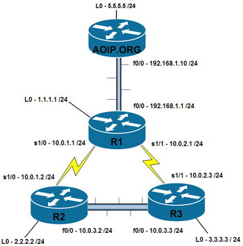
In yesterday’s post ‘Static Routing’ we saw that we needed to create a static route to allow the Cisco router “AOIP.ORG” to ping “R2”. The static route that we created was ‘ip route 10.0.1.0 255.255.255.0 192.168.1.1’ and ping was successful to the IP address 10.0.1.2 (R2’s Serial interface). The problem with that configuration was that ping would still not work to the rest of our network, and we would have to create a static route for every other network address that we have.
Luckily for us, the Cisco Router “AOIP.ORG” only has one way in or out for traffic to flow, and that is through its FastEthernet 0/0 interface. When a network segment only has one way in or out, it is known as a ‘Stub Network’. The good news with Stub networks is that since there is only one way in or out, we don’t need to run routing protocols or make tons of static routes to teach the router how to get to possibly hundreds of networks since they will all have the same exit point. This is where creating a default gateway of last resort is useful.
The default gateway of last resort is the last option the router will choose if no other routes match. In our example below, there are currently no routes on ‘AOIP.ORG’ so it’s only able to send packet to networks directly connected to it (192.168.1.0 and 5.5.5.0). Since there are no other routes, the default gateway of last resort is the only route and hence the route that will be matched in all cases.
You will see in the live demo below, I tried to ping the IP address 2.2.2.2 which is the loopback interface of R2. Ping was not successful as there are no routes configured on the router and 2.2.2.2 is not directly connected. The router then has no choice but the drop the packet as it doesn’t know what to do with it. You will then see I configured the default gateway of last resort ‘ip route 0.0.0.0 0.0.0.0 192.168.1.1’. This is the standard format for the default gateway of last resort and tells the router that a packet needing to get to any network anywhere must be sent to the next hop of 192.168.1.1 (R1’s FastEthernet 0/0 interface). Ping is then successful as our router is told to send packets with any destination not directly connected to our router to R1.
Note: Cisco Routers will also look for the closest match in the routing table, so if a better match existed in the routing table it would have chosen the better route.
Note: Routing had already been configured on R1, R2 and R3 in the below example.


